A Trustworthy PCB and Electronic Manufacturing Enterprise! Contact Us


Fly probe testing is currently the optimal solution for addressing key challenges in automated pcb testing. It replaces needle beds with probes, utilizing multiple motor-driven electrical probes capable of rapid movement to make contact with device pins and perform electrical measurements.
During PCB production, external factors inevitably cause electrical defects such as short circuits, open circuits, and leakage. Coupled with the continuous evolution of PCBs toward higher density, finer pitch, and multi-layer designs, failing to promptly screen out defective boards and allowing them to enter the manufacturing process will inevitably lead to increased cost wastage. Therefore, beyond process control improvements, enhancing testing technology offers PCB manufacturers solutions to reduce scrap rates and boost product yield.
Electrical testing methods include: Dedicated, Universal Grid, Flying Probe, Non-contact Electron Beam (E-Beam), conductive fabric (adhesive), capacitive, and brush testing (ATG-SCANMAN). Among these, three commonly used devices are dedicated testers (PCB automatic universal testers), high-quality universal testers, and flying probe testers.

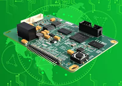
automated pcb testing
What distinguishes Flying Probe testing from test fixtures? What are their respective advantages in automated pcb testing?
Flying Probe Testing: This method employs 4 to 8 probes to perform high-voltage insulation and low-resistance continuity tests on circuit boards, detecting open circuits and short circuits without requiring dedicated test fixtures. The PCB is directly mounted onto the Flying Probe tester, and testing commences upon running the test program. The advantages of flying probe testing lie in its extremely convenient testing method and operational workflow. It reduces testing costs, eliminates the time required to manufacture test fixtures, and improves shipping efficiency, making it suitable for small-batch PCB production.
Test fixtures, on the other hand, are specialized testing jigs designed for continuity testing of mass-produced PCBs. While their manufacturing costs are higher, they offer better testing efficiency and do not incur charges for reorders. Regarding test technology applicability, flying probe testing is currently suitable for electrical testing of small-volume production and samples. However, when applied to medium-to-large-scale production, its slow test speed and high equipment cost significantly increase testing expenses. In contrast, both universal and dedicated testers achieve economies of scale for any PCB layer level once production volume reaches a certain threshold, with testing costs typically accounting for only 2-4% of the unit price. This is why universal and dedicated testers are the primary choices for mass production testing equipment today. Working Principle of Flying Probe Testers The flying probe tester is an improvement over traditional needle bed inline automatic high-voltage dedicated PCB board testers, replacing the needle bed with probes.
During operation, the Unit Under Test (UUT) is conveyed into the tester via a belt or other UUT transport system. The tester's probes are then fixed to contact the test pads and vias, enabling testing of individual components on the UUT. Test probes connect to drivers and sensors via a multiplexed transmission system to test components on the UUT. While one component is being tested, other components on the UUT are electrically shielded by the probe system to prevent reading interference.
Flying probe testers can inspect for shorts, opens, and component values. A camera is also employed in flying probe testing to assist in locating missing components. The camera is used to verify the orientation of directional components, such as polarized capacitors.
With probe positioning accuracy and repeatability within the 5-15 micron range, flying probe testers enable precise detection of the Unit Under Test (UUT). Flying probe testing resolves numerous existing challenges encountered in PCB assembly: potentially lengthy test development cycles of 4-6 weeks; the inability to economically test small production batches; and the inability to rapidly test prototype assemblies. Flying probe testing is a method for verifying the electrical functionality of PCB boards (open/short circuit testing). A flying probe tester is a system for testing PCBs in a manufacturing environment. Unlike traditional bed-of-nails interfaces used on conventional in-line testers, flying probe testing employs four to eight independently controlled probes that move to contact components under test. The unit under test (UUT) is conveyed into the tester via a belt or other UUT transport system. It is then secured, and the tester's probes contact test pads and vias to test individual components on the UUT. Test probes connect via a multiplexing system to drivers (signal generators, power supplies, etc.) and sensors (digital multimeters, frequency counters, etc.) to test components on the UUT. While one component is being tested, other components on the UUT are electrically shielded via the probe system to prevent reading interference.
1. Charge/Discharge Time Method The charge/discharge time (also known as net value) of each network is constant. If networks have equal net values, a short circuit may exist between them. Only networks with identical net values need to be measured for shorts.
The testing procedure is as follows: For the first board: Full open-circuit test → Full short-circuit test → Net value learning; For subsequent boards: Full open-circuit test → Net value test. Where a short-circuit is suspected, the resistance method is used for verification. The advantages of this testing method are accurate results and high reliability. The disadvantages are that the first board takes a long time to test, requires multiple re-tests, and has low testing efficiency. The most representative example is MANIA's SPEEDY machine.
2. Inductance Measurement Method This method operates by using one or more large networks (typically ground planes) as antennas. Signals applied to these antennas induce inductance in adjacent networks. The tester measures the inductance of each network and compares these values. Identical inductance values indicate potential short circuits, prompting further short circuit testing. This method is only suitable for boards with ground planes. Testing double-sided boards (without ground planes) yields unreliable results. When multiple large-scale networks are present, efficiency drops because multiple probes are used for signal application, reducing the number of probes available for testing. The advantage is higher testing reliability and fewer rework cycles. The most representative equipment is ATG's A2 and A3 models. To compensate for the limited number of probes, these machines are equipped with 8-pin and 16-pin configurations to enhance testing efficiency.
3. Capacitance Measurement Method This method is similar to the charge/discharge time method. Based on the relationship between conductive patterns and capacitance, if a reference plane is set, the distance from the conductive pattern to it is L, and the area of the conductive pattern is A, then C = εA/L. An open circuit is indicated when the conductive pattern area decreases, reducing the corresponding capacitance. Conversely, a short circuit occurs when two conductive pattern sections connect, increasing the capacitance response. During open circuit testing, capacitance values at each endpoint of the same network should be equal. Unequal values indicate an open circuit. Record each network's capacitance value for comparison during short circuit testing. The advantage of this method is high testing efficiency. Its limitation is complete reliance on capacitance, which is influenced by numerous factors, resulting in lower testing reliability compared to the resistance method. Particularly, measurement errors caused by associated capacitance and secondary capacitance reduce reliability for networks with fewer endpoints (e.g., single-point networks). Currently, flying probe testers from HIOKI and NIDEC READ employ this testing method.
Fly probe testing does well in automated pcb testing.