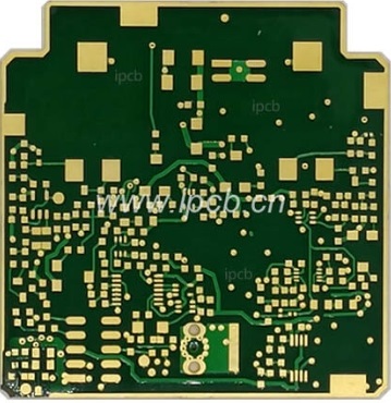
A radar PCB (printed circuit board) is a special type of circuit board designed for use in radar systems. It sends and receives radio signals to detect objects and measure parameters such as distance and speed. These boards connect vital components, such as antennas, transmitters, receivers, and signal processors, ensuring the smooth operation of the radar system. Since it uses high-frequency signals, radar PCBs must be carefully constructed to maintain the strength and stability of these signals. Types of radar PCB include single-pulse radar PCB, Doppler radar PCB, weather radar PCB, passive radar PCB, and pulsed radar PCBs. Weather radar PCBs detect and analyse weather conditions using RF signals.
Conventional weather radars PCB include rain radars, cloud radars, and wind radars. A weather radar is a type of meteorological radar, also known as a rain measurement radar. It is the main tool used for detecting and forecasting medium- and small-scale rainfall systems and issuing alerts. The weather radar PCB works by transmitting electromagnetic pulse waves into space via a highly directional antenna and utilising the scattering effect of raindrops, cloud droplets, ice crystals, snowflakes, and so on on the electromagnetic waves. This allows the concentration and distribution of precipitation in the atmosphere or large drops in the clouds to be detected, as well as typhoons, strong winds in local areas, hailstones, rainstorms, and strong convective clouds. It can also be used to monitor weather movement and evolution, and to understand the structure of weather systems.

weather radar pcb
Classification of weather radar PCB
Radar can be categorised into different bands, such as S-, C-, and X-band. Radar PCB with a lower frequency usually has a wider search range, but its accuracy is reduced accordingly. For example, S-band radar, which has a frequency range of 2–4 GHz, has strong penetrating power and is therefore suitable for long-term monitoring of rainstorms and hurricanes. It is commonly used in fixed Weather Bureau stations.
According to the different methods of radar detection, weather radar PCBs can be divided into phased array, Doppler, and dual polarisation radar. Doppler radar PCB detects the speed at which an object is moving by measuring the change in signal frequency. It is used in speed detectors, motion sensors, and weather radars. Phased array radar uses multiple antennas to electronically control the signal instead of physically moving the antennas. It scans faster and is used in 5G technology, missile tracking, and advanced radar systems. Conventional Doppler radar is horizontally polarised and cannot identify the type of precipitation, whereas dual-polarisation radar uses both horizontal and vertical polarised waves to enable the classification and identification of precipitation.
The weather radar PCB has several features:
-Excellent high-frequency performance: support X-band, C-band and even K-band RF signal transmission, the material is usually Rogers, Taconic, Isola and other high-frequency copper-clad laminates.
-Multi-layer structure design: often 8-layer, 12-layer or even 16-layer high multilayer boards to support complex signal transmission and shielding layout.
-High reliability requirements: To cope with field or high altitude operation, it must have the ability to resist high humidity, corrosion, and wide temperature operation (-40°C to +85°C).
-Precise impedance control: Due to the high signal frequency, the transmission line impedance requirements are extremely strict, usually within ±5% error control.
The parts of a PCB weather radar are:
1. Transmitter: The signal from the waveform generator is not strong enough for the radar. The transmitter makes the signal stronger using something called a power amplifier.
2. Receiver: The radar receiver's job is to make the weak echo signal from the antenna stronger and change it into a video signal to be sent to the display to make the echo signal.
3. Antenna: The radar antenna's job is to send out high-frequency pulse waves in a certain direction and then receive echoes from that direction. The weather radar PCB in meteorology is usually made up of two parts, a radiation horn and a reflector.
4. Antenna transmission device: This is made up of two parts. One part is part of the antenna rotation system. The other part is part of the synchronisation system. The antenna rotation system's job is to turn the antenna around to detect the plane and the vertical structure of the precipitation and cloud distribution. The antenna synchronization system makes the cathode ray tube consistent with the different moments of the scanning baseline of the azimuth, elevation and the corresponding time. This means that the antenna is always pointing in the same direction (i.e., synchronised).