A Trustworthy PCB and Electronic Manufacturing Enterprise! Contact Us


The USB Hub PCB board is a circuit board specially designed to increase the number of USB ports on a device. This product makes a USB port into several output ports. It does this by using a USB Hub Controller chip, connector, and related circuits. This allows users to connect multiple USB devices (such as USB flash drives, mice, keyboards, etc.) at the same time. Most USB hubs that you can buy are covered by a shell, while the USB hub PCB board is an exposed circuit board core. You can customize the functions, size, and interface type of the USB hub PCB (such as Type-A or Type-C).

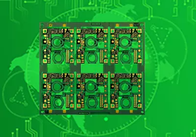
usb hub pcb board
Key Components in USB Hub PCB Design
-Shielding: This is an important part of USB hub PCB board design. It protects the signal section from high noise. If there is a lot of noise around, it can damage the connector.
-Strong Power Connection: This design puts the power pins on the USB connector. It allows the connection to be done before the data lines. This helps avoid powering the device over the data lines, which can be dangerous for USB.
-Polarization: Most connectors are only able to go in one direction. If you don't install the connector into a device the right way, it can damage the device.
-Strain Relief: It's a plastic coating on the USB that prevents tension on the cable and avoids damaging the electrical connection.
-Four Contacts: USB designs have at least four contacts. However, some designs have five or more contacts, such as 3.0+ USB connectors.
List of Materials and Tools
-USB Connector: Choose a connector that meets your needs, such as USB 2.0 or USB 3.0.
-Hub Body: You can use plastic or metal to make the hub shell.
-Circuit Board (PCB): It is the main electronic component, the mounting substrate of the hub.
-Soldering Tools: This includes soldering pens, solder wires, and soldering stations. These tools are used to connect electronic components and circuit boards.
--Advanced Tools: This includes heat guns, multimeters, and oscilloscopes.
--Measuring Tools: This includes tools like rulers and calipers that are used to make sure that components and circuit boards are the right size.
-Design Tools: KiCad is free and open source, while Altium Designer has a professional version.

usb hub pcb board
Steps for designing
Step 1: Create a schematic design.
-Choose the USB controller chip;
-Draw the schematic diagram and check it to make sure it's correct.
Step 2: Design the PCB's layout and path for the wires.
-Put the power module, controller chip, and USB port in different areas.
-Determine the size, number of layers, and routing rules of the PCB. This will meet the needs and specifications of the USB hub PCB board.
Step 3: Create production files
-Make Gerber files based on the PCB layout that was designed;
-List all the component models, packages, and quantities, and make a list of the parts;
Fabrication and Soldering
-Submit all your files to the PCB manufacturer-iPCB. Then, choose the right manufacturing process and materials.
-The manufacturer will use chemical methods, copper plating, etching, and other steps to make a PCB board with a circuit copper layer and an insulating layer.
-Add silk screen, pads, and other special requirements to the USB hub PCB board so that you can install and solder other components later.
-There are two ways to solder: manual or SMT (surface mount technology). When soldering, it's best to start with the small components and then move on to the large ones.
Testing and Quality Control
Electrical testing
Electrical testing of USB hubs PCB board is done using the right tools. We test the connector connectivity to make sure all the interfaces are working properly. We also test the signal stability and speed to make sure the data transmission is reliable.
Functional Test
Test the different parts of the USB hub, like data transfer, charging, and connecting other devices. Make sure the hub works normally in different situations, like connecting multiple devices or transferring data at the same time.
Quality Control
Make sure the soldering is correct and firm to avoid poor contact or loose parts. Check the quality of the shell assembly to make sure it looks intact and has no obvious defects. Also, check that the product marking and labeling are correct to make sure it complies with relevant standards and requirements.
Reliability testing
Test the USB hub in different situations to make sure it's stable and reliable over time. Check its resistance to vibrations, pressure, and magnets to ensure it's durable and reliable in real-world use.
USB hubs are an important part of the process to meet the demands of modern data connectivity. The USB hub PCB board is made in a way that ensures it works well and can be trusted. This process includes getting the materials and tools ready, designing the circuit, making the parts, putting it all together, and testing it to make sure it works.