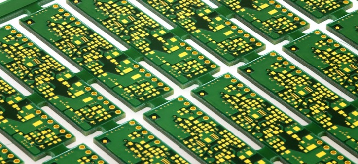
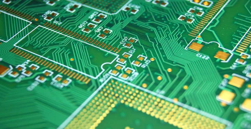
This guide covers everything from what a PCB is, how to understand the components of a PCB, to how to read pcb board.
PCBs are often considered to be the backbone of electronic devices. Almost all electronic devices have PCBs as their main components, such as smartphones, laptops, game consoles, washing machines, and other everyday electronic devices. One of the key attributes of an electronics engineer is to understand the complex layout of a PCB, which can only be achieved through a basic understanding of basic electronic components, circuit theory, and circuit troubleshooting and debugging. Understanding basic electronic components and their configuration techniques in a circuit can help with circuit analysis and effective troubleshooting.
Printed Circuit Board (PCB):
A PCB is a circuit board with conductive copper wires and various electronic components. These electronic components are connected to each other with the help of copper wires to form a complete closed-loop circuit through which current flows through the circuit, which is why PCBs are considered to be the backbone of electronic devices. It is important to understand what types of different electronic components are used in PCBs and what they are used for. In addition, it is important to understand which combination of electronic components must be used to achieve the desired electrical goals. It is very important to know how to read a PCB board.

how to read pcb board
In general, electronic components are divided into two categories based on their function.
Passive components
Active components
Passive components:
As the name suggests, passive components are not used to regulate or enhance the electrical signals transmitted to such elements, these components are only used to conserve energy or react. Below is a list of passive components and a brief introduction.
Resistance: This element is used to block electric current, and its resistance value is measured in ohms. Resistors are one of the most commonly used electronic components. There is a color code on its body from which the resistance value can be calculated. There are various types of resistors, such as potentiometers, thermistors, and potentiometers, which have different power ratings, such as quarter-watts, half-watts, and one-watts, which can be used according to the needs. Usually, "R" is used as an indicator on PCB screen printing, which indicates a resistor.
Capacitors: The passive components used to conserve energy in the electric field are capacitors, which are usually denoted by a "C" on the PCB. Capacitors are measured in farads, such as millifarads, microfarads, nanofarads, picofarads, and vice versa. Different types of capacitors are used for different purposes in PCB designs, such as electrolytic capacitors are used in designs that require very high capacitance to block DC signals, paper capacitors are used to allow AC signals and vice versa.
Inductor: This passive component stores energy in the form of a magnetic field. In contrast to capacitors, inductors store energy until the closed-loop electronic circuitry is intact. In PCB, the "L" is used as an indicator for the inductor, measured in Henry.
2. Active Ingredients:
These elements can modulate or enhance the electrical signal, unlike the passive components discussed earlier. Listed below are some of the main source components that are commonly used in PCBs.
Diode: A semiconductor device that is mainly used to control a unidirectional voltage and restrict the flow of electrical signals in the wrong direction so as not to damage the circuit, so it can be used as a protective diode. Diodes are usually denoted by the letter "D" in PCBs. Applications include signal processing, power control, and light emission.
Transistors: In modern electronics, transistors are considered the most important component of a design. It can act as an electronic switch and amplifier. A transistor is a three-legged electronic component, i.e., a collector, base, and emitter. There are billions of transistors in a single IC. PCB designers provide random designators for transistors as they wish, but typically use "Q" or "VT" in PCBs. Different types of transistors are used in PCB designs, such as MOSFET, FET, JFET, and bipolar transistors.
How to read PCB board?
At first glance, a PCB appears to be a very complex circuit board with many electronic components connected together with intricate wiring. Engineers need to read PCBs efficiently in order to reverse engineer or debug them. The following steps must be followed to know how to read the PCB correctly.
Identifying components: Reading a PCB starts with a visual inspection of the PCB, looking at resistors, capacitors, ICs, transistors, and other electronic components. Different symbols are used for different components. Usually, these codes are fixed for a particular component, as mentioned earlier, e.g. "R" for resistor, "L" for inductor, and vice versa.
Interpreting markings on components: This involves decoding alphanumeric codes or resistor color codes on electronic components to know their ratings. Most capacitors have alphanumeric codes from which one can find their capacitance ratings, and resistors have color codes that represent their resistance in ohms.
Understanding Component Layout: This step is also very important for reading the PCB board. This step involves understanding why and how different components are placed in such a pattern. In general, those components that emit heat in their surroundings should be kept away from heat-sensitive components or circuits. In this way, this step helps to understand the PCB design constraints for more efficient reading of the PCB.
Understanding PCB Routing: Identifying the Conductive Copper Path that connects components in a PCB. With these traces, different components can communicate and perform required functions, such as amplifying voltage signals, providing power and ground signals to different ICs, and vice versa. This step also helps to understand and analyze the signal flow in the circuit. By focusing on the PCB at the signal propagation level, circuit troubleshooting and its optimization becomes easier.
Defect and error checking: It is important to inspect the PCB because damaged stitches, warped pads, and misaligned components can all cause PCB failures.
Document findings and observations: When reading a PCB, it's a good idea to create a document of your findings and observations. This document may include component ratings and indicators, which can also help create the BOM. This document will help with future troubleshooting and debugging, modifying, and revising PCB versions.

how to read pcb board
Summary
Reading PCBs is an art, and it's important for electronic design engineers to master this essential skill that how to read pcb board to improve related skills like troubleshooting, testing, and enhancing PCB design. How do I read a PCB? By simply following the steps above, electronics engineers can improve their PCB reading abilities and literacy to meet modern challenges and increase their precision, accuracy, and confidence in complex PCBs.