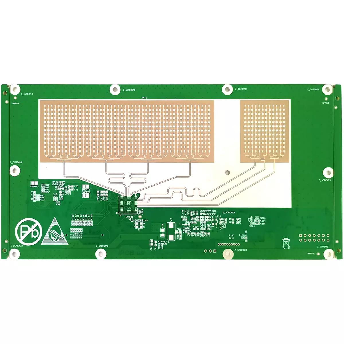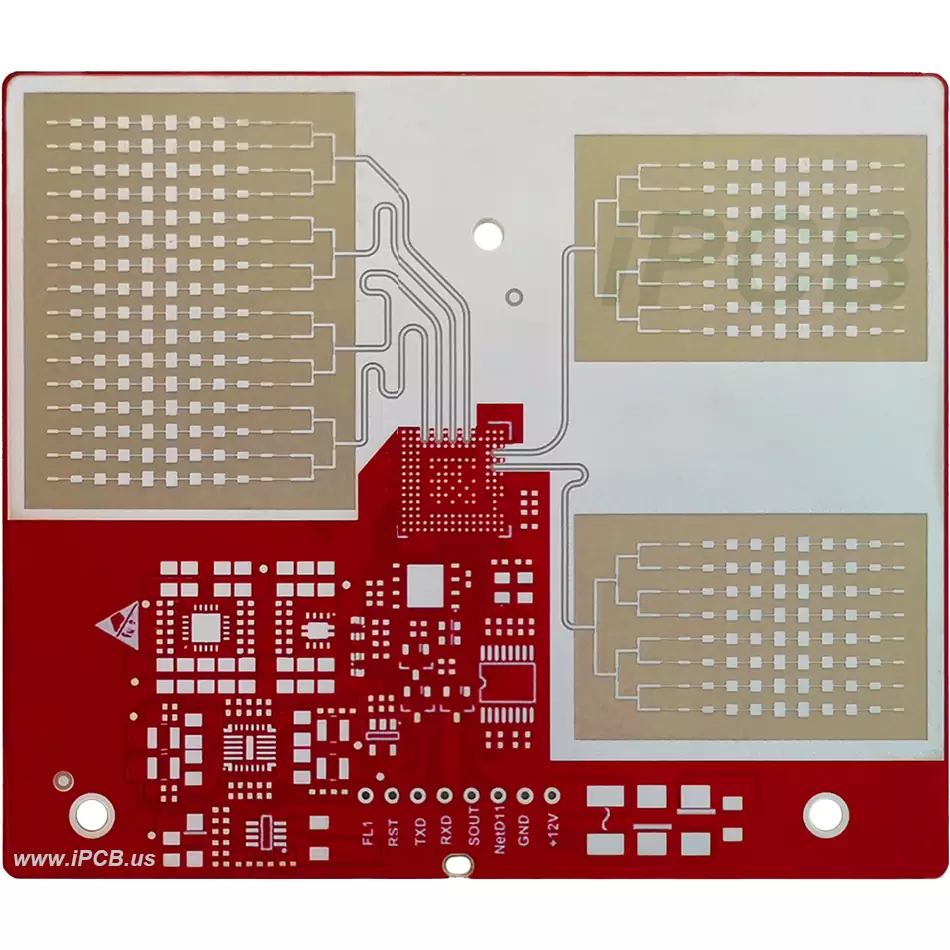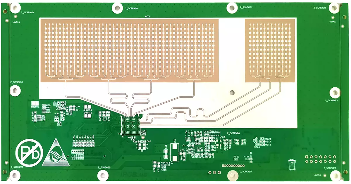

Product: Millimeter Wave Radar PCB
PCB Substrate: Rogers RO3003G2+Isola 370HR
Quality standard: IPC6012 class2 or class3
DK of substrate: 3.00+/-0.04mm
PCB Layers: 4Layers - 12Layers
Copper thickness: 1/1oz
Thickness: 1.2mm - 2.0mm
PCB structure: with blind holes
Surface treatment: Silver, EING or OSP
Product application: Millimeter wave radar
What is millimeter wave radar PCB?
1. Working on radar for millimeter wave detection. The working frequency range is generally between 30GHz and 300 GHz, with a wavelength of 1-10mm, which is between microwave and centimeter wave, and has some advantages of microwave radar and optoelectronic radar.
2. The PCB circuit board used for products that use millimeter wave radar as a detection method is the millimeter wave radar PCB.
3. Millimeter wave radar has the characteristics of small size, easy integration, and high spatial resolution compared to centimeter wave radar.
4. The operating frequency of vehicle mounted millimeter wave radar is generally 24GHz and 77GHz
The basic structure of millimeter wave radar
Hardware core: MMIC chip and antenna PCB. Taking FMCW vehicle radar system as an example, it mainly includes antenna, transceiver module, and signal processing module
Front end single-chip microwave integrated circuits (MMICs) include various functional circuits, such as low noise amplifiers (LNAs), power amplifiers, mixers, and even transceiver systems.
Features: Low circuit loss, low noise, wide frequency band, large dynamic range, high power, high additional efficiency, strong resistance to electromagnetic radiation, etc.
Radar antenna high-frequency PCB: The mainstream solution for millimeter wave radar antennas is microstrip arrays, which integrate high-frequency PCBs onto ordinary PCB circuit boards to achieve antenna functionality. It is necessary to maintain sufficient signal strength of the antenna in a small integration space.
Basic working principle of millimeter wave radar
1. Using high-frequency circuits to generate electromagnetic waves with specific modulation frequencies (FMCW), and transmitting and receiving electromagnetic waves reflected back from the target through an antenna, the parameters of the target are calculated based on the parameters of the transmitted and received electromagnetic waves.
2. It can simultaneously measure distance, speed, and azimuth for multiple targets. Speed measurement is based on the Doppler effect, while azimuth measurement (including horizontal and vertical angles) is achieved through an array of antennas.

Millimeter wave radar PCB
The working system of millimeter wave radar
1. Working system: According to the different ways of radiating electromagnetic waves, millimeter wave radar mainly has two working systems: pulse system and continuous wave system. Continuous wave can be divided into FSK (frequency shift keying), PSK (phase shift keying), CW (constant frequency continuous wave), FMCW (frequency modulated continuous wave) and other methods.
2. Different modulation forms of FMCW frequency modulated continuous wave radar: a、 Sine wave modulation b, sawtooth wave modulation c, triangular wave modulation
The hardware composition of radars with different frequency modulation methods is basically the same, with only a small number of circuit modules, circuit parameters, and signal processing algorithms differing. For the measurement of a single stationary object, the sawtooth modulation method is sufficient. For moving objects, triangular wave modulation is often used.
Principles of millimeter wave radar ranging, lateral velocity, and azimuth measurement
Distance measurement: (TOF) is achieved by continuously sending millimeter wave signals to the target, and then using sensors to receive the millimeter waves returned from the object. The distance to the target is obtained by detecting the round-trip time of the millimeter waves.
Speed measurement: Based on the Doppler effect, the relative velocity of the target relative to the radar can be obtained by calculating the frequency change of the radar wave returned to the receiving antenna. Simply put, the relative velocity is proportional to the frequency change.
Measurement of azimuth angle: The azimuth angle of the target is calculated by receiving the phase difference of radar waves reflected by the same target through parallel receiving antennas.
Comparative Analysis of 24GHz vs 77GHz Millimeter Wave Radar
24GHz millimeter wave radar
1. The frequency band from 24.0GHz to 24.25GHz is narrowband (NB) with a bandwidth of 250MHz, commonly used in industry, science, and medicine. Among them, the 24GHz frequency band also includes an ultra wideband (UWB) with a bandwidth of 5GHz.
2. In short-range radar, NB and UWB radars in the 24GHz frequency band have been applied to traditional automotive sensors. Usually, NB radar can perform simple applications such as blind spot detection, but in most cases, including ultra short distance situations, UWB radar is required due to the need for high-frequency resolution.
3. However, due to the spectrum rules and standards established by the European Telecommunications Standards Institute (ETSI) and the Federal Communications Commission (FCC), the UWB frequency band will soon be gradually phased out. After January 1, 2022, UWB frequency bands will no longer be used in Europe and the United States, and only narrowband ISM frequency bands can be used for a long time.
77GHz millimeter wave radar
1. The 76-77GHz frequency band can be used for remote vehicle radar, and this frequency band has the advantage of equivalent isotropic radiated power (EIRP), which can be used for front-end remote radar, such as adaptive cruise control.
2. The 77-81GHz Short Range Radar (SRR) frequency band is a newly added frequency band. This frequency band has recently gained significant appeal in terms of global regulation and industry adoption.
3. This frequency band can provide a wide scanning bandwidth of up to 4 GHz, making it ideal for applications that require high range resolution (HRR).
Comparison of the Performance of 24GHz and 77GHz Millimeter Wave Radar in Vehicles
1. Different frequencies, the wavelength of 24GHz millimeter wave radar is greater than 10cm, strictly speaking, it belongs to centimeter wave radar.
2. Compared to 24GHz, 77GHz satisfies both high transmission power and wide operating bandwidth, allowing it to achieve long-distance detection and high distance resolution simultaneously.
3. Compared to 24GHz, 77GHz has significant advantages in object resolution, velocity measurement, and distance measurement accuracy.
4. Compared to 24GHz, 77GHz radar has a smaller volume with a wavelength of less than one-third of 24GHz, resulting in a significant reduction in the area of the transmitting and receiving antennas and an effective decrease in the overall size of the radar.
Compared to cameras and LiDAR, the advantages of millimeter wave radar
1. All day, all-weather working characteristics - regardless of day and night, not limited by weather conditions, can work normally even in rainy and snowy days.
2. Strong environmental adaptability, able to work normally in adverse weather conditions - strong penetration ability, with minimal interference from rain, fog, dust, and other factors on millimeter wave radar.
3. Strong speed and distance measurement capabilities.

millimeter wave radar
For the millimeter wave radar PCB of autonomous driving perception hardware such as millimeter wave radar, the protective material of the millimeter wave radar PCB also needs to meet high-precision control requirements such as low transmission loss, low transmission delay, and high characteristic impedance. At present, commonly used engineering plastics have excellent strength, flame retardancy, electrical insulation and other properties after modification, and are widely used in fields such as automobiles, electronic appliances, and household appliances.
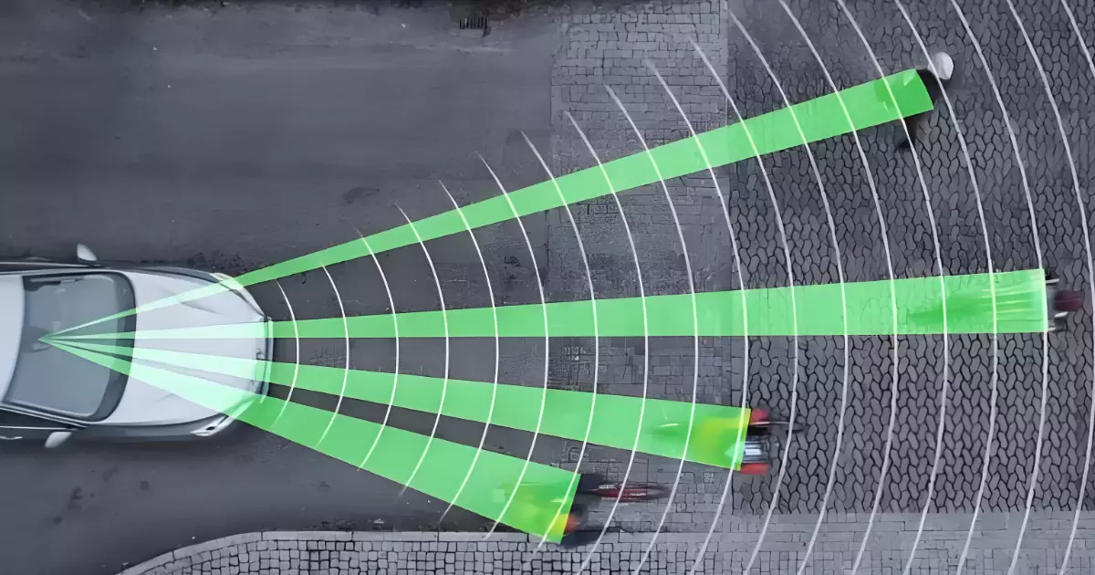
Millimeter wave radar has been widely used in the automotive industry, including various aspects from safety to comfort performance, such as blind spot detection, lane changing assistance, automatic cruise control, and parking assistance. Regardless of the weather and surrounding lighting conditions, millimeter wave radar can reliably and accurately detect and locate obstacles.
Product: Millimeter Wave Radar PCB
PCB Substrate: Rogers RO3003G2+Isola 370HR
Quality standard: IPC6012 class2 or class3
DK of substrate: 3.00+/-0.04mm
PCB Layers: 4Layers - 12Layers
Copper thickness: 1/1oz
Thickness: 1.2mm - 2.0mm
PCB structure: with blind holes
Surface treatment: Silver, EING or OSP
Product application: Millimeter wave radar
iPCB Circuit provides support for PCB design, PCB technology, and PCBA assembly. You can request technical consultation or quotation for PCB and PCBA here, please contact email: sales@ipcb.com
We will respond very quickly.