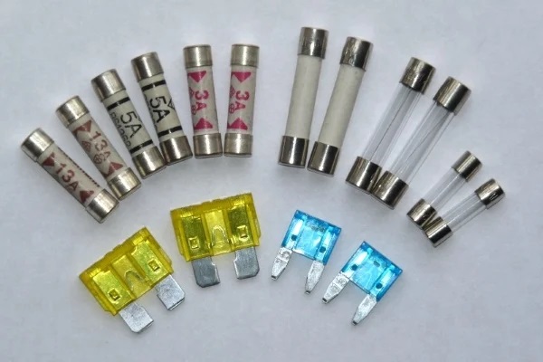
When your smartphone experiences a sudden voltage fluctuation while charging, or your laptop unexpectedly suffers an electrical surge during a thunderstorm, have you ever wondered what is silently protecting these expensive electronic devices? The answer is that unassuming yet crucial “unsung hero”—the PCB board fuse. In today's era of increasingly complex and miniaturized electronic devices, even a few milliseconds of current overload can render an entire motherboard inoperable. As the first line of defense in circuit protection, the PCB board fuse bears a tremendous responsibility within its tiny package, ensuring your devices can operate safely in the face of various electrical threats.

pcb board fuse
A PCB board fuse is a small sacrificial device that is directly integrated into a printed circuit board to protect the circuit from excessive current. When the current exceeds the fuse's rated value, its internal components (typically metal wires or strips) melt, thereby breaking the circuit and preventing damage to downstream components. This rapid interruption minimizes risks such as overheating, component failure, and even fire hazards.
Whether you are designing consumer electronics, automotive systems, or industrial machinery, understanding how to select the right pcb board fuse is key to optimizing performance and safety. Let's delve into the details of overcurrent protection and how to choose the perfect PCB fuse for your application.
Types of PCB Fuses
There are many types of PCB board fuses, each type tailored to meet particular application needs and performance criteria. Having a good grasp of these fuse classifications is essential when it comes to choosing the most suitable fuse for your design. The following are the most common types of PCB fuses:
By Fusing Characteristics
1. Fast-acting fuses: Protect semiconductor devices sensitive to current changes (such as ICs, transistors) or resistive load circuits that do not generate surge currents. They respond very quickly to overload currents and have no design-related delay
2. Slow-acting fuses: Can handle temporary surge currents exceeding the component's rated current. They do not blow until they receive a sustained high current exceeding their rated current for a specific time before operation.
By structure and packaging
1. Surface-mount fuses: Compact devices directly soldered to the PCB surface. Their small size, light weight, and compatibility with automated assembly processes make them a popular choice for space-constrained consumer electronics and high-density PCB board fuse designs.
2. Through-hole mount fuses: Commonly used in industrial control, power supply, and some older designs. Advantages include high mechanical strength, relatively easy manual replacement, and the ability to handle higher voltages and currents.
By recoverability
1. One-time fuses: Use a metal fuse structure that melts and breaks the circuit when overcurrent occurs. They feature fast response, high precision, and low cost. Suitable for use as primary protective devices, but require replacement after melting.
2. Resettable fuses: Based on polymer positive temperature coefficient materials, they increase resistance to limit current during overcurrent conditions and automatically reset after the fault is eliminated. They offer maintenance-free and reusable advantages but have slower response times, making them suitable for precision electronic products where replacement is difficult.
Best Practices for PCB Board Fuse Integration
1. The optimal location for fuses in a circuit
Fuses are typically placed upstream of the power input, as close as possible to the power connector, so that the entire circuit can be isolated as early as possible in the event of a fault. Consider whether PCB board fuses are needed on each power rail.
2. PCB layout considerations
-Trace width: PCB traces connecting the fuse pads must be wide enough to carry the rated current without overheating, to prevent the trace itself from becoming a "second fuse".
-Safety clearance: Ensure that the PCB board fuse and its pads have sufficient electrical clearance and creepage distance from other conductive parts, especially in high-voltage applications, to prevent arcing.
-Maintainability: For fuses that may need to be replaced (especially through-hole types), they should be placed at the edge of the PCB or in an easily accessible location.
3. Handling of pulse and surge currents
Compare the calculated surge I²t with the fuse's melting I²t to ensure the fuse can withstand normal startup pulses. Typically, the fuse's I²t value should be at least 2-3 times the surge I²t value.
Selecting The Most Reliable PCB Board Fuses
Choosing the most reliable PCB board fuses helps provide greater protection for PCBs, electronic equipment, industrial control systems, and circuit designs. All aspects of electronic circuit design must be considered to ensure effective protection through the selection of the correct PCB fuses. Some key considerations when selecting the appropriate PCB fuses are:
-Rated current
-Rated voltage
-Fuse type
-Temperature factors
-PCB fuse size and shape
-Speed and time response
-Fuse certification
-Cost analysis
In the field of electronic system design, selecting the appropriate PCB board fuse is a critical task that directly affects the reliability, safety, and efficiency of system operation. Engineers must have a comprehensive and in-depth understanding of the various types of fuses, accurately grasp key selection criteria, and be proficient in best practices for integration. Only then can they effectively protect circuits from overcurrent events and extend the service life of equipment.