Are you interests in pcb doppler radar? Let us see the pcb doppler radar how to role.
1. Basic knowledge
Radar
Radar is the abbreviation of Radio Detection and Ranging. It originally means radio detection and ranging. It is a device that uses radio (electromagnetic waves) to detect targets and determine their spatial positions. With the development of radar technology, modern radar can not only locate targets, but also measure the speed of targets, image targets, and even measure the size and material properties of targets. However, the theoretical basis of all the principles of using radar waves to detect the speed of objects is derived from the "Doppler effect".
For a detailed introduction to radar, please click here
Doppler theory
Waves are composed of frequency and amplitude, and radio waves move with objects. When radio waves hit objects during their travel, the radio waves will be bounced back, and the frequency and amplitude of the waves that bounce back will change with the movement state of the objects they hit. If the object that the radio wave hits is fixed, the frequency of the radio wave that bounces back will not change. However, if the object moves in the direction of the radio line, the radio waves bounced back will be compressed, so the frequency of the radio waves will increase; conversely, if the object moves away from the radio waves, the frequency of the radio waves bounced back will decrease.

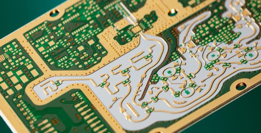
pcb doppler radar
2. Fourier transform
In most applications of Fourier transform, we use discrete Fourier transform (DFT), or more precisely, its fast algorithm FFT. The following is a brief introduction to what these Fourier transforms are and what is the connection.
2.1 Fourier transform
A linear integral transform can be understood as a change from time to frequency or their mutual conversion, which transforms the signal from the time domain to the frequency domain, and then studies the spectral structure and change law of the signal.
3. Two commonly used radar sensors
Next, we introduce two commonly used radar sensors K-LC6 and K-MC1. Used to measure the existence, speed, direction of movement, and distance information of objects.
K-LC6
24GHz radar sensor, with VCO narrow beam K-band radar sensor. A dual channel Doppler radar module for short to medium range sensors. Suitable for motion and presence sensors for people and vehicles.
Detection range: People > 24m; Vehicles > 62m. (Close range)
● The module includes an RF low noise amplifier (LNA) for optimal signal to noise performance. Dual IF I and Q allow for motion direction detection and high performance signal processing.
K-MC1
24GHz radar sensor with VCO narrow beam K-band radar sensor, 60 patch Doppler module for long range sensors.
Detection range: People 56m; Vehicles > 150m. (Long range)
● The module includes an RF low noise amplifier and two 47dB IF preamplifiers for I and Q channels. This feature will significantly reduce the need for external analog electronics. For special signal condition applications, additional buffered mixer DC outputs are provided. This greatly increases the flexibility of FSK ranging applications.
Working principle: The generation and reception of RF signals of K-LC6 and K-MC1 radar modules are integrated. It uses a voltage-controlled oscillator to generate a 24GHz RF oscillation signal, and after power amplification through the transmission channel, it is transmitted through a microstrip antenna; once the transmitted RF signal hits the target, it is reflected, and the reflected signal is received by the receiving antenna. After amplification and demodulation in the receiving channel, a zero intermediate frequency signal is obtained, and further amplified by the intermediate frequency amplifier to obtain a beat intermediate frequency output containing the target Doppler speed information with a certain signal-to-noise ratio.
Both K-LC6 and K-MC1 can measure speed, but K-MC1 can measure distance while measuring speed
4. FFT Doppler radar speed measurement principle
The pcb Doppler radar sensor outputs an analog voltage signal containing the speed and direction of the object by transmitting and receiving RF oscillation signals. The output signal of the module is filtered and amplified and connected to the AD input pin of the stm32 microcontroller. The DSP math library of stm32 is used to implement complex FFT transformation to obtain the Doppler difference frequency, and the speed and direction of the current object are obtained based on the difference frequency.
Note that the pcb doppler radar module will output two signals, which are divided into real and imaginary parts. One signal can only calculate the speed, and two signals can calculate the direction of the speed. The simultaneous sampling of the two signals can use the STM32 dual ADC simultaneous conversion mode, and use the timer to trigger, and control the current sampling frequency by changing the pre-loaded value of the timer.

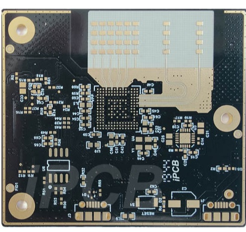
pcb doppler radar
The orthogonal signal amplitude output by the module is relatively small at a long distance. If you want to increase the detection distance of the module, you need to add an operational amplifier circuit. In addition, since the output of the RF module has a DC bias, we currently choose to add a DC blocking capacitor to the front end of the op amp and add a potentiometer for zero adjustment.
Do you know pcb doppler radar better after reading this article?