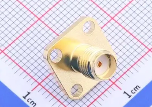
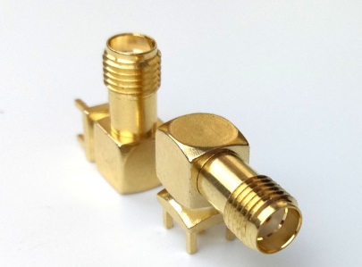
RF antenna connector are commonly found in our IoT electronic devices. They typically connect one end to the antenna and the other to the mainboard. The quality of these connectors directly impacts the transmission quality and reliability of the signal.
Below, we will analyze the four most commonly used RF antenna connectors encountered in our work: SMA, N-type, BNC, and IPEX.
RF Antenna Connector Performance
The function of RF antenna connectors is to achieve low-loss, high-reliability signal transmission in RF connections while ensuring the stability of mechanical connections. Skin effect at high frequencies: When the signal frequency exceeds 1 GHz, current concentrates on the surface of the conductor, reducing the effective cross-sectional area and increasing loss. Connectors must optimize surface treatment through gold plating and insulating materials to reduce loss; Power capacity limitations: High-power signals generate heat inside the connector, requiring increased contact area and optimized heat dissipation design to prevent damage; Mechanical stability: Factors such as vibration, temperature changes, and insertion/removal cycles may cause connection loosening, necessitating structural designs like threads or latches to enhance reliability.
Performance metrics: Frequency range
The highest frequency that can be reliably transmitted; Impedance: Standard RF systems use 50 ohms, while video and some cable TV systems commonly use 75 ohms; Power capacity: The maximum continuous RF power the connector can withstand; Insertion loss: Energy loss of the signal as it passes through the connector; Voltage standing wave ratio (VSWR): A metric for measuring signal reflection; Mechanical life: Number of insertion/removal cycles.
1.IPEX IPEX is a miniature board-to-wire, board-to-board RF connector primarily used within devices to connect antennas (such as WiFi/BT/GPS/NFC PCB antennas or external antennas) to the main RF module.
Extremely small size: The smallest among all listed connectors, currently divided into five generations: IPEX 1 to IPEX 5, primarily differing in size. Designed for high-density PCBs.

rf antenna connector
• Frequency range: IPEX connectors typically operate from DC to 6 GHz. Specifically designed for consumer electronics frequency bands such as WiFi 2.4 GHz/5 GHz, Bluetooth, GPS, and 4G LTE. Impedance: 50 ohms.
• Connection method: Surface mount or through-hole soldering on the PCB.
Power capacity: Very low. Suitable only for small-signal transmission within devices. Durability: Relatively low. Primarily used for connections during factory assembly and allows for a few during repairs. Frequent can easily cause damage. Applications: Smartphones, tablets, laptops (built-in WiFi/BT antennas), wireless routers (internal antenna connections), GPS modules, 4G/5G modules, smartwatches, IoT sensor nodes. FPC antennas and PCB antennas.
• Advantages: Extremely compact and lightweight, suitable for high-density PCB designs, excellent high-frequency performance in consumer electronics frequency bands, low cost with large production volumes.
• Disadvantages: Limited number of insertion/removal cycles, extremely low power capacity, designed for internal fixed connections only, not suitable for external removable interfaces.
2. SMA

rf antenna connector
One of the most commonly used small RF connectors, especially in the mid-to-high frequency bands.
Compact size: Extremely compact, suitable for space-constrained applications (e.g., routers, small modules, internal board-to-board connections).
• Frequency range: DC - 18 GHz (standard quality);
• Impedance: 50 ohms is the absolute standard.
• Connection method: Threaded locking (male connector with external threads, female connector with internal threads).
• Power capacity: Moderate.
• Durability: Moderate. Standard SMA design supports approximately 500 mating cycles.
• Applications: Extremely versatile: WiFi routers/network cards, Bluetooth devices, GPS modules, walkie-talkies.
• Advantages: Compact size, relatively low cost.
• Disadvantages: Fine threads prone to cross-thread damage; durability inferior to larger connectors; limited power capacity;
3. BNC
BNC connectors are snap-in quick-connect connectors for small to medium-sized applications.
• Size: Smaller than SMA but larger than N-type connectors.
• Frequency range: DC to 4 GHz (standard quality).
• Impedance: Available in 50 ohm and 75 ohm versions.
• Connection method: Bayonet-style (the male connector has two lugs, and the female connector has a slot; rotating approximately 60 degrees locks/unlocks the connection). Insertion and removal are extremely quick and convenient.
• Power capacity: Low to medium. Lower than SMA and N-type. Suitable for low-power signal transmission.
• Durability: Moderately high. The bayonet design is relatively durable.
• Applications: Test and measurement instruments: oscilloscope probes and signal generator outputs are the primary applications.
• Advantages: Quick insertion/removal, convenient for frequent connection/disconnection, low cost, and 50/75 ohm physical compatibility.
• Disadvantages: Low upper frequency limit, low power capacity, and the bayonet design may be unreliable under strong vibration.
4. Type N
Type N connectors are medium-sized, robust, high-performance connector standards.
• Size: Much larger than SMA.
• Frequency range: DC - 11 GHz (standard quality); high-quality (precision) versions can reach 18 GHz. Performance is very stable and excellent below 11 GHz.
• Impedance: 50 ohms is the most common version.
• Connection method: Threaded tightening. Provides excellent mechanical stability, vibration resistance, and environmental sealing.
• Power capacity: High. Standard N-type connectors can easily handle hundreds of watts or even kilowatts of average power (in the low-frequency band), making them an ideal choice for base station antenna feedlines and medium-power applications.
• Durability: High. The design typically supports over 1,000 mating cycles, ensuring high durability and reliability.
• Applications: Cellular base station antenna feedlines, microwave relays, broadcast transmission equipment, test equipment: network analyzers and spectrum analyzers, etc.
• Advantages: Robust and durable, high power capacity, excellent electrical performance (low loss, low reflection).
• Disadvantages: Larger size and weight, higher cost.
Do you knwo these types of rf antenna connector?