A Trustworthy PCB and Electronic Manufacturing Enterprise! Contact Us


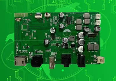

Product: RF PCB Assembly
Material: FR4, Rogers (RO4003C/RO4350B), PTFE, ceramic (AlN)
Quality standard: IPC-6012 Class 3, IEC 61189, RoHS 3.0
Dielectric constant: 2.0–10.1 @1–100GHz
Layers: 2–12 layers
Thickness: 0.1–2.4mm
Copper thickness: 1–5 oz
Surface technology: ENIG, hard gold plating
Special requirements: 1MHz–280GHz, 50Ω, ≤0.6dB insertion loss @28GHz, -55℃~125℃
Application: 5G/6G, radar, automotive ADAS, satellite communication
Every time you connect to 5G, use a radar system, or rely on satellite communication—you’re counting on RF PCB Assembly to keep signals strong, clear, and loss-free. Unlike standard PCBs that struggle with electromagnetic interference (EMI) and signal degradation at high frequencies, this specialized assembly is built to tackle the unique pain points of radio frequency transmission: minimizing attenuation, maintaining impedance balance, and withstanding extreme operating conditions.
Why Standard PCBs Fail at High Frequencies (And RF PCBs Fix It)
High-frequency signals (1MHz–280GHz) are fragile—they lose strength, pick up interference, or mismatch with components easily. RF PCB Assembly addresses these issues head-on:
Fighting Signal Loss: Standard FR4 PCBs lose too much signal at 5G’s 28GHz, but RF variants use Rogers RO4003C/RO4350B (ultra-low loss, tanδ=0.0028–0.0038) to keep attenuation ≤0.6dB at 28GHz. For 6G’s 100GHz+ bands, PTFE substrates (tanδ=0.0003) cut loss even further, ensuring data reaches its destination without degradation.
Avoiding Impedance Mismatch: A 50Ω impedance mismatch can reflect 30% of a signal—wasting power and distorting data. RF PCB Assembly uses 2–12 layer designs with 1–5oz copper traces, laser-drilled microvias (0.1mm), and tight dielectric constant (Dk=2.0–10.1) control to lock in 50Ω (or 75Ω/100Ω) impedance, reducing reflection loss to < -20dB at 10GHz.
Withstanding Harsh Environments: Military radar needs to work in -55℃ arctic conditions; 5G base stations endure 125℃ desert heat. Ceramic (AlN) RF PCBs handle this with thermal conductivity up to 195 W/m·K, while ENIG or hard gold plating protects against corrosion in coastal or dusty sites.

RF PCB Assembly
How RF PCB Assembly Is Tailored to Specific Frequency Needs
No two RF applications are the same—so the assembly is customized to match the frequency band and use case:
Sub-1GHz (Wi-Fi Routers, AM/FM Radios): Cost-effective FR4-based RF PCBs (Dk=4.2–4.6) balance performance and budget for low-frequency needs.
5G/6G (Base Stations, mmWave Devices): Rogers substrates (Dk=3.4–3.5) deliver the stability required for 28GHz–100GHz signals, supporting multi-gigabit wireless speeds.
Extreme Environments (Military Radar, Satellites): Ceramic (AlN/Si₃N₄) RF PCBs (Dk=9.7–10.1) resist temperature swings (-55℃~125℃) and EMI, critical for mission-critical systems.
Real-World Impact: RF PCBs in Action
Telecom: 5G small cells use Rogers-based RF PCBs to extend coverage in urban areas, cutting signal dropouts by 40% compared to standard PCBs.
Automotive: ADAS radar (77GHz) relies on RF PCBs to detect obstacles 200m away, enabling automatic emergency braking.
Aerospace: Satellite transceivers use ceramic RF PCBs to send data back to Earth—even through space’s extreme temperature shifts.
Built to Meet Global Standards (And Future Demands)
Every RF PCB Assembly complies with IPC-6012 Class 3 (for mission-critical precision), IEC 61189 (RF performance testing), and RoHS 3.0. It’s also future-ready: integration with GaN/SiC semiconductors boosts power handling, while AI-optimized trace routing reduces crosstalk for next-gen 6G and terahertz systems.
Product: RF PCB Assembly
Material: FR4, Rogers (RO4003C/RO4350B), PTFE, ceramic (AlN)
Quality standard: IPC-6012 Class 3, IEC 61189, RoHS 3.0
Dielectric constant: 2.0–10.1 @1–100GHz
Layers: 2–12 layers
Thickness: 0.1–2.4mm
Copper thickness: 1–5 oz
Surface technology: ENIG, hard gold plating
Special requirements: 1MHz–280GHz, 50Ω, ≤0.6dB insertion loss @28GHz, -55℃~125℃
Application: 5G/6G, radar, automotive ADAS, satellite communication
iPCB Circuit provides support for PCB design, PCB technology, and PCBA assembly. You can request technical consultation or quotation for PCB and PCBA here, please contact email: sales@ipcb.com
We will respond very quickly.