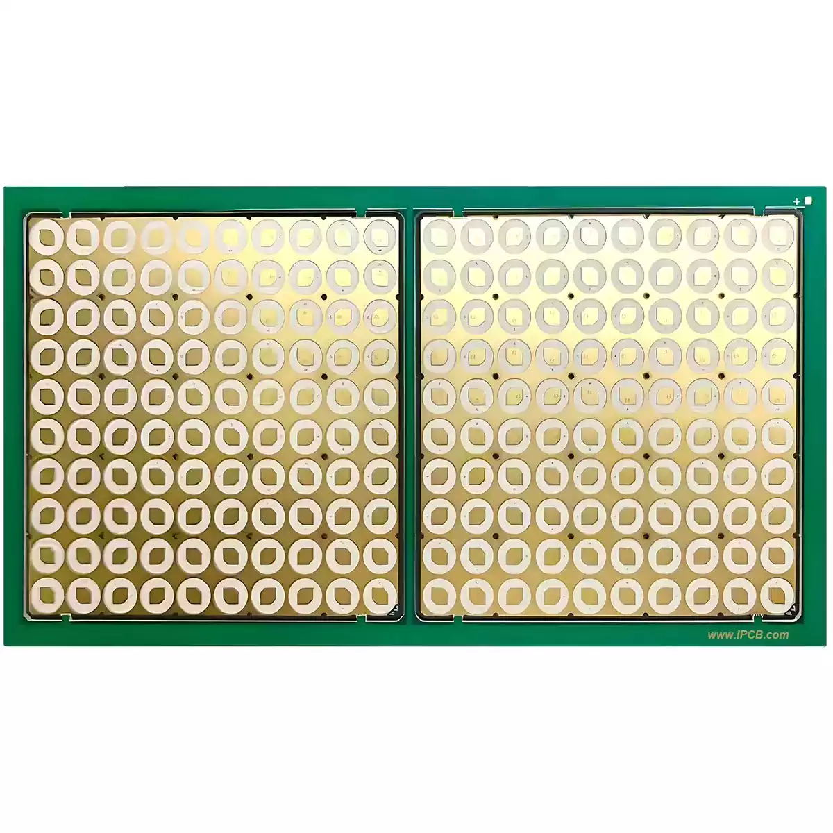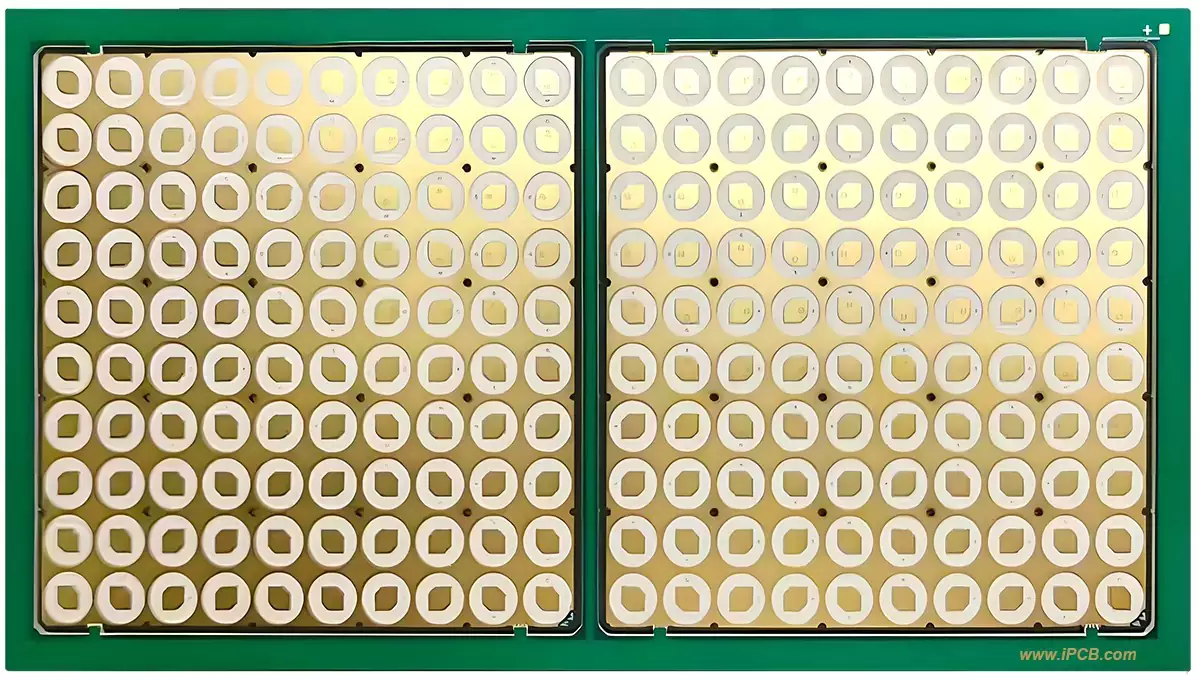
Product : High-Frequency PCB
Materials: Rogers RO4003C
Quality Standard: IPC-6012 Class 2 / Class 3 (supports blind/buried vias & impedance control)
DK of Substrate: 3.38±0.05 at 10 GHz
PCB Layers: 4–12 Layers
Copper Thickness: ½ oz to 1 oz (standard foil).
Thickness:
- Base material: 0.203 mm – 1.524 mm
- Finished thickness: 0.6 mm – 2.0 mm (after lamination)
PCB Structure: Blind/buried vias supported (FR4-compatible fabrication)
Surface Treatment: OSP, Immersion Silver, ENIG (high-frequency preferred)
Product Applications: 5G base station antennas/power amplifiers, millimeter-wave radar, satellite communication, high-speed server backplanes
Special Notes:
- No UL94V-0 rating (select RO4350B for flame-retardant requirements).
- Z-axis CTE = 46 ppm/°C (ensures multi-layer thermal stability).
Choose an excellent solution for your critical high-frequency designs. Our Rogers RO4003C PCB manufacturing service delivers unmatched electrical performance and reliability, and is certified to the highest industry standards. RO4003C is a ceramic-filled hydrocarbon-based laminate, suitable for applications with strict requirements for signal integrity, low loss, and stable dielectric properties.
We process this high-quality material into complex multi-layer circuit boards, providing core power for the next generation of wireless technology. Advanced manufacturing processes ensure precise impedance control and outstanding quality, making us a trusted partner for well-known enterprises in the aerospace, telecommunications, and automotive radar fields.

RO4003C PCB
Technical Specifications & Capabilities:
PCB Substrate: Rogers RO4003C Laminate
Dielectric Constant (Dk): 3.38±0.05 at 10 GHz (exceptional lot-to-lot consistency)
Dissipation Factor (Df): 0.0027 at 10 GHz (ultra-low signal loss)
Quality Standard: IPC-6012 Class 2 / Class 3 (meets the rigorous requirements for high-reliability applications)
Layer Count: 4-12 Layers (utilizes RO4400-series prepregs for robust multi-layer bonding)
Copper Thickness: Standard electrolytic copper foil, with thickness ranging from ½ oz to 1 oz
Thickness Range:
Core Material: 0.203 mm (8 mils) - 1.524 mm (60 mils)
Finished Board: 0.6 mm - 2.0 mm after lamination
Advanced Structures: Full support for blind vias, buried vias, and impedance control (tight tolerance of ±10% or better)
Surface Finishes:
Electroless Nickel Immersion Gold (ENIG) - recommended for high-frequency performance scenarios
Immersion Silver
Organic Solderability Preservative (OSP)
Thermal Reliability: Z-axis Coefficient of Thermal Expansion (CTE) is 46 ppm/°C, ensuring excellent plated through-hole integrity and thermal stability in multi-layer structures
Product : High-Frequency PCB
Materials: Rogers RO4003C
Quality Standard: IPC-6012 Class 2 / Class 3 (supports blind/buried vias & impedance control)
DK of Substrate: 3.38±0.05 at 10 GHz
PCB Layers: 4–12 Layers
Copper Thickness: ½ oz to 1 oz (standard foil).
Thickness:
- Base material: 0.203 mm – 1.524 mm
- Finished thickness: 0.6 mm – 2.0 mm (after lamination)
PCB Structure: Blind/buried vias supported (FR4-compatible fabrication)
Surface Treatment: OSP, Immersion Silver, ENIG (high-frequency preferred)
Product Applications: 5G base station antennas/power amplifiers, millimeter-wave radar, satellite communication, high-speed server backplanes
Special Notes:
- No UL94V-0 rating (select RO4350B for flame-retardant requirements).
- Z-axis CTE = 46 ppm/°C (ensures multi-layer thermal stability).
iPCB Circuit provides support for PCB design, PCB technology, and PCBA assembly. You can request technical consultation or quotation for PCB and PCBA here, please contact email: sales@ipcb.com
We will respond very quickly.