A Trustworthy PCB and Electronic Manufacturing Enterprise! Contact Us


Luminous inverters are critical for reliable power backup, and at the heart of their performance is the PCB. The luminous inverter PCB controls the central command unit, which regulates technicians and procurement specialists. A deep understanding of this component is vital for efficient sourcing and maintenance. This guide breaks down the PCB's essential structure, functionality, and key purchasing considerations within a concise framework.
1. Detailed Anatomy of the Luminous Inverter PCB
The PCB is a multi-functional system comprised of distinct, specialized circuits.

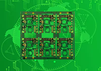
luminous inverter pcb
1.1. Control & Processing Core
The system is governed by a Microcontroller (MCU) or Digital Signal Processor (DSP). This chip runs the complex firmware, precisely managing the switching sequences required for AC generation, monitoring all system parameters (voltage, current, temperature), and executing diagnostic fault codes. The DSP is particularly key for generating high-quality Pure Sine Wave output.
1.2.The Power Conversion Stage
This section is responsible for converting DC battery power into usable AC power.
---MOSFETs/IGBTs: These are the high-power semiconductor switches configured in an H-bridge. They are rapidly switched on/off by the control core to create the alternating current.
---Thermal Management: Due to the heat generated during conversion, the PCB incorporates robust copper tracing and heat sink mounting points. Integrated thermal sensors communicate with the MCU to prevent catastrophic overheating failures.
1.3.Intelligent Charging and Protection
---Adaptive Battery Charging Technology (ABCT): The PCB implements multi-stage charging (Bulk, Absorption, Float) to prevent overcharging and deep discharge, significantly extending the battery's lifespan.
---Protection Circuits: Current-sensing circuits provide instantaneous protection against overload and short-circuit conditions, while voltage monitors protect both the battery and the load from dangerous fluctuations.
2. Functional Excellence and Key Features.
The PCB is a multi-functional system comprised of distinct, specialized circuits.
2.1. Pure Sine Wave Output
The precision of the luminous inverter PCB's DSP allows it to synthesize a utility-grade Pure Sine Wave. This clean waveform is essential for sensitive electronic loads (computers, medical equipment), ensuring they run cooler, quieter, and without distortion.
2.2. Reliability and Durability
Beyond active protection, durability is built into the design:
---Efficiency: High-efficiency component layout minimizes energy loss as heat, increasing battery runtime.
---Conformal Coating: High-quality boards often feature a conformal coating to protect against moisture, dust, and corrosive elements, which is critical for reliability in harsh environments.
3. Troubleshooting and Maintenance Essentials
Effective issue resolution starts with PCB diagnostics.
3.1. Interpreting Diagnostic
---The PCB relays status through LED/LCD indicators: Continuous Beep/Shut Down: Often indicates a short-circuit or heavy overload, usually tied to failure in the power stage (MOSFETs).
---Low Battery Warning: Indicates the charging circuit on the luminous inverter PCB may be faulty or the battery has reached its low-voltage cutoff point.
3.2. Preventive Measures
---Ventilation: Ensure optimal airflow around the inverter to reduce thermal stress on the components.
---Visual Inspection: Regularly check the PCB (with power disconnected) for common failures like burned MOSFETs or bulging capacitors.
---Load Management: Operating below 80% maximum capacity reduces thermal and electrical stress, prolonging component life.
4. Sourcing the Right Luminous Inverter PCB
Procurement requires precision to ensure compatibility and quality.
4.1. Model Identification
Always identify the exact inverter model and VA rating. The most reliable method is to use the unique PCB Part Number printed on the board itself, as this number correlates directly with the correct firmware and transformer settings.
4.2. Quality and Procurement Checklist
Buyers must weigh OEM against high-quality aftermarket options.
---Compatibility: Ensure the replacement PCB revision is compatible with the inverter’s original transformer and shell.
---Component Grade: Verify that the supplier uses industrial-grade MOSFETs and capacitors to maintain system performance and longevity.
---Pre-Programming: Confirm the board is pre-programmed with the correct firmware for the specific VA rating. A mismatch in programming will lead to operational errors.
---Secure Shipment: Always demand anti-static packaging to protect the sensitive electronics during transit.
5. Conclusion
The luminous inverter PCB is the non-negotiable component that dictates the inverter's quality, efficiency, and safety. Mastering its anatomy and maintaining its integrity ensures peak performance and a reliable, uninterrupted power supply. Correct identification and procurement of a high-quality replacement board are paramount for maximizing the lifespan of the entire system.