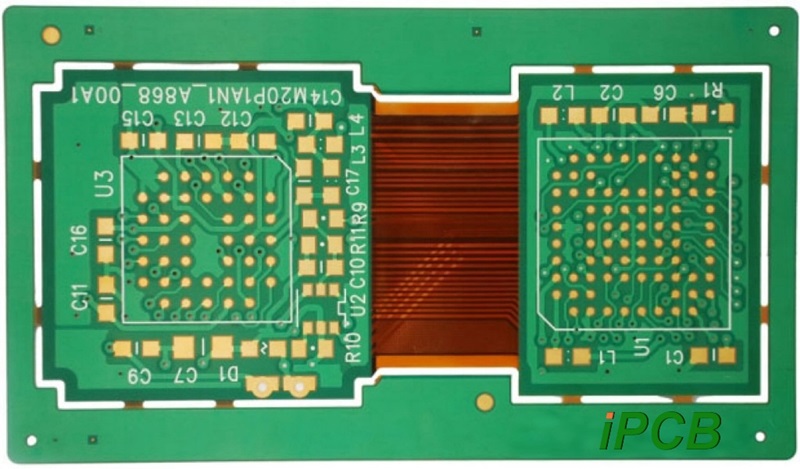
Rigid-flex boards are hybrid boards that combine elements of both flexible and rigid boards, resulting in a board that is foldable or continuously curved, and is often formed into curved shapes or curves during the manufacturing process. Rigid-flex circuit boards have a flexible layer buried within the board and penetrating the rigid portion of the PCB. Rigid-flex boards are typically thinner than other circuit boards, which means that it is possible to use thin copper layers and adhesive-free laminates to meet the needs of any thin and light package.
Rigid-flex circuit boards are slightly more complex to design because they are designed in 3D and can therefore be folded or twisted to create the shape required for the product. The 3D design means that they are space-efficient and can therefore be used in specialised applications where space and weight savings are required, such as medical devices.

rigid flex circuit
The manufacturing process for rigid-flexible circuit panels involves several steps, such as material preparation, drilling, plating, etching, and stripping. The starting part of any rigid-flexible circuit board is usually a single or double-sided flexible layer. Manufacturers can start with a pre-pressed foil flex board, or they can start with an unclad PI film, which is then laminated or copper plated for the initial cladding. Laminated films require a thin layer of adhesive, while non-adhesive cladding requires a copper ‘seed layer’. This seed layer is initially deposited using a vapour phase deposition technique (e.g., sputtering) and provides the key support for the chemically deposited copper plating. The drilling, plating, and etching steps for such single- or double-sided flexible circuits are much the same as for a typical double-sided core board in a rigid board.
Types of Rigid-Flex PCBs
Flex-to-Install: These are designed to be bent only once during installation or repair.
Dynamic Flex: These are designed for continuous bending and flexing during normal operation.
Rigid-flex circuit design has several advantages
1. Space Efficiency: Rigid flex circuit boards are very space efficient because they eliminate the need for connectors and reduce the need for additional interconnections. They can be folded or bent to fit into tight spaces, making them ideal for compact and densely arranged electronic devices.
2. Reliability: The fewer connectors there are, the fewer potential points of failure, which improves overall system reliability. Rigid-flex PCBs are less prone to connector-related problems.
3. Durability: Rigid-flex PCBs are designed to withstand mechanical stress, vibration, and temperature changes, making them suitable for use in harsh environments.
4. Reduced Assembly Costs: Despite the initial complexity of the manufacturing process, rigid flex circuit boards can often be assembled at a reduced cost due to fewer components and manual assembly steps.
5. Complex geometries: Rigid-flex technology enables the creation of complex board shapes and three-dimensional configurations that are difficult to achieve with conventional PCBs.
Challenges in Designing Rigid-Flex PCBs
1. Complex design rules: The design rules for rigid-flex circuit boards are often more complex than those for rigid PCBs. There is a need to understand the mechanical and electrical requirements of both rigid and flexible parts, including bend radius, layer stacking, and material constraints.
2. Bend Radius Considerations: One of the key aspects of rigid-flex design is determining the proper bend radius for the flexible part. Selecting a bend radius that is too small can lead to mechanical failures and signal integrity issues.
3. Material Selection: It is critical to select the right material for both the rigid and flexible portions of the PCB. Different materials have different coefficients of thermal expansion, which can lead to reliability issues during temperature changes.
4. Signal Integrity and EMI: Maintaining signal integrity and controlling electromagnetic interference (EMI) in flexible parts can be challenging. The flexibility of the substrate and the proximity of the signal to the flexed area can affect signal quality.
5. Connector Location: Determining where the connector transitions between rigid and flexible sections is a critical design decision. Improper connector placement can lead to mechanical stress and reliability issues.
6. Layer Transitions: Properly transitioning a signal layer from a rigid section to a flexible section can be challenging. Misalignment or improper layer transitions can lead to impedance mismatches and signal degradation.
7. Assembly and Manufacturing: The assembly process for rigid-flex circuit boards can be more complex than rigid boards. Designers must consider how the board will be assembled and ensure that components are properly placed and soldered.
8. Mechanical Reliability: Ensuring that the flexible part can withstand repeated bending and flexing without mechanical failure is critical, especially in applications such as wearable or foldable devices.