Flex pcb design offers many advantages, but also new design challenges.
What is FPC flexible circuit board?
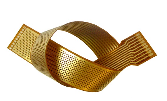
FPC flexible circuit board is a type of circuit board made of flexible substrate, which is not only lightweight, but also able to bend and fold. Flex pcb design allows it to excel in tight spaces or irregularly shaped electronic devices. Imagine that future smart watches, folding screen phones, and even wearable devices have the potential to become thinner, more portable, and more durable because of the presence of FPC flexible circuit boards.
Unlike "standard" 2D circuit boards, PCB design engineers are affected by a number of specific issues when designing flexible circuit boards. Understanding the characteristics of flexible circuit board design can help you solve problems ahead of time and speed up the design cycle.
What is Flex PCB Design?
There is no doubt that almost all electronic devices need a PCB to function properly. However, as technology advances, the need for smaller packages and weight limits has made flexible circuit boards more prevalent in design. This method pairs the conductor with a flexible insulating film, allowing it to carry the signals required for operation and remaining flexible: its ability to bend and bend allows it to be not only an electronic device, but also a mechanical device. This approach was first applied to space programs with the aim of saving weight and space when performing missions, and was soon applied to the military and consumer sectors.
How to choose the right type for your application?
There are two types of flex circuits: flex boards and rigid-flex boards.
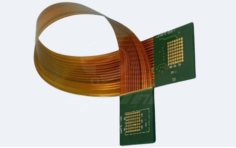
1.The former allows the device to be mounted on a flexible plastic substrate, while the latter is a combination of flexible and rigid circuitry. The combination of rigid-flex designs absorbs the best of both worlds: the rigid board carries most of the devices, while the flexible part connects them.
2.In recent years, with the demand for circuits for smaller, higher-performance electronic products, the trend of rigid flexible and flex pcb design has grown exponentially; Smartphones and tablets are good examples. Flexible circuit board design is also taking over many other high-end consumer electronics segments,and the future is limitless.

flex pcb design
There are two types of use for flex circuits: static and dynamic
Static flex circuits are used for the least bending frequencies, usually during use and assembly.
Dynamic circuits are used in frequently bent end systems, such as the hinge of a laptop or a printer head. Differentiating the end use of a product is critical to ensuring that the circuit is constructed using the right materials and stacking methods.
Choose your materials wisely
A wide variety of materials are used to build a flexible circuit.
These materials include films, copper foils, and adhesives. More commonly polyester and polyimide, the choice of material depends on how and under what circumstances the circuit is assembled and used. Some materials may have additional advantages or disadvantages, depending on our specific design intent. When building a flexible circuit, carefully consider material selection and consult with the manufacturer to achieve the best possible decision.
Design considerations
There are a number of key design elements that must be considered when designing rigid-flex PCBs.
Every design theme is prone to serious accidents, so our choice is very important. More often than not, projects are mostly in progress for a long time before a big mistake is discovered, and the team has to backtrack and rework on the problem. As a result, flexible, easy-to-use, and feature-rich tools are needed to help us quickly identify problems in complex designs and lead us on the right path to successful design.
Cascade
There are several flexible stackup configurations, each with its own capabilities.
A single-layer circuit is mounted on a single-conductor layer made of metal or conductive polymer, covered over a flexible dielectric film. Single-layer circuits are currently the most commonly used and least expensive type of circuit. Single-layer circuits have a thin structure and are most effective in situations where constant motion is required.
The double-layer circuit is placed on two conductor layers, and its main advantage is the ability to mount components on both sides of the board. Use this type when shielding applications is important to your design.
Multilayer circuits span three or more layers that may not be continuously stacked together throughout the structure and may have openings or cavities. This type is more common in the case of dense circuit installation and assembly.
A rigid-flex structure is a combination of flexible circuits placed on a rigid and flexible substrate. After that, they will be laminated into a single structure, ideal for applications in areas where stability and flexibility are required.
layout
There are different layout requirements for the flexible and rigid areas of the board, which are unique to flexible circuit board design.
Smart component layout is the ability to place a component in a rigid or flexible area and automatically place it on the highest component layer in that area. In both flexible states, we also need to check the clearance between the z-axis elements.
Bending areas and layer structures
Special consideration is required for the bending area, especially on the bend line of a flex circuit. To reduce the pressure, the trace needs to pass through a bend area perpendicular to the bend line. Traces on adjacent layers should be offset to avoid the formation of I-beams. Designers must be able to set face and overlap constraints between objects on different layers. For example, pins and vias should not be in or near the bend area to prevent cracking.

flex pcb design
The layer structure (also known as the horizontal section) is set according to the design requirements. In a rigid-flex design, not all areas of the board contain all layers. In general, there are fewer wiring layers in flexible areas than in rigid areas. We have to make sure that we avoid routing in areas where layers don't actually exist.
Flex circuits present a unique set of challenges when wiring.
The bending ability of the circuit means that it has special design requirements. Routing considerations and functional requirements include: arc corner routing, sliding functionality for arc editing, and the ability to convert corners to arcs. Here's a brief overview of these routing strategies, how long they're in use, and how important they are to flex board design.
Arc corner routing is the ability to route traces that have curved angles rather than orthogonal (45°) angles. Flex board design requires the use of curved traces to route the bus lines to reduce stress, so we must use arcs for routing.
Pads have specific requirements to ensure robustness and longevity.
All pads, including surface mount and vias, should be fastened to prevent the copper from separating from the substrate material. All pads should also have rounded corners to reduce stress points and eliminate breakage during bending. The quality of these components will determine how long the end-user product will last and therefore need to be carefully checked.
Three-dimensional inspection, bending and bending
Essentially, flex board design adds a layer of physical complexity.
The complication lies in the process of checking the final bending state of the circuit. All elements must be precisely laid out so as not to collide or interfere with each other in any part of the bend. Therefore, a design tool that can analyze the fit and clearance of bent circuits in 3D is essential. Ideally, the analysis can be done by the designer, preferably in two phases: during and after the bend finish state. This helps to spot problems in both states and alerts us to problems that arise in between.
After reading this article, do you have a better understanding of flex pcb design?