A Trustworthy PCB and Electronic Manufacturing Enterprise! Contact Us



Universal PCBs are circuit boards designed and manufactured according to standard specifications to ensure compatibility with various types of components and applications. Unlike circuit boards custom-designed for specific products or systems, universal PCBs provide a reusable platform that can be adapted to a wide range of electronic projects with only minor modifications. The availability of universal PCBs accelerates the prototyping process for electronic devices and equipment and simplifies the development process.
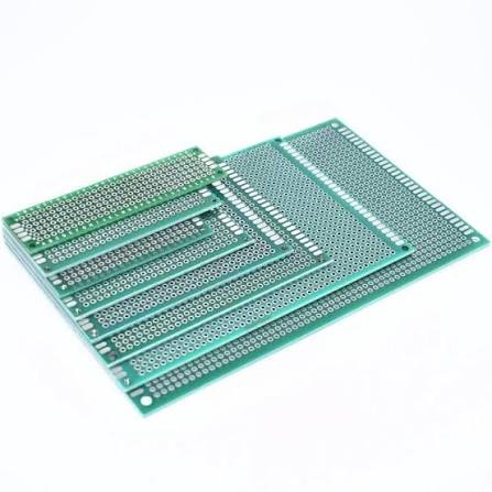
universal pcb
Standard Specifications for Universal PCBs
Most universal PCBs adhere to industry standards, ensuring compatibility with commonly used components and connectors. Understanding these specifications helps you select the appropriate circuit board and ensures your components can be mounted correctly.
1. Standard Dimensions
Universal PCBs follow a set of standard dimensions for length, width, and thickness. Common sizes for general-purpose boards include: 100 x 160 mm; 100 x 220 mm; 160 x 233 mm.
2. Hole Grid and Pitch
The standard hole pitch is 2.54 mm (0.1 inch), arranged in rows and columns, and is suitable for DIP-packaged integrated circuits, connectors, and pin sockets. This pitch dates back to early integrated circuit packaging and remains the mainstream standard for through-hole components today.
3. Plated Through-Holes vs. Single-Sided Pads
Plated through-holes (PTH) connect copper pads on both sides of the circuit board, enhancing mechanical strength and allowing for routing on both surfaces. Single-sided pads are simpler and less expensive, but are limited to a single working surface and offer weaker solder joint strength.
4. Standard Hole Sizes
Common drill bit diameters range from 0.8 to 1.0 millimeters, suitable for component leads with diameters of 0.5 to 0.8 millimeters. This is particularly important when working with thicker leads, such as those found on power resistors or terminal blocks—please verify that your circuit board can accommodate these leads before purchasing.
Types of Universal PCBs
Universal PCB is a general term that encompasses a variety of different circuit board types, including standardized formats such as OCA. OCA is widely used in modular systems due to its compatibility and dimensional specifications. Each type of circuit board has its own specific advantages, depending on the complexity of the circuit, assembly skills, and project requirements.
1. Perforated Boards
These are characterized by individual copper pads surrounding each hole, forming a uniform matrix. Unlike custom PCBs, which use etching chemicals to remove excess copper and create specific copper traces, universal boards have no pre-connected traces—each connection must be made manually. Circuit connections can be made via point-to-point jumpers, by bending component leads and soldering them between pads, or by using insulated wire to connect the board. This approach offers maximum flexibility but also requires careful planning.
2. Strip Boards
One side of a strip board features long, parallel copper traces arranged along the holes. These copper traces act as pre-fabricated buses that can automatically connect multiple points. They are easier to “read” and debug than the randomly arranged wiring of universal boards. However, they offer less flexibility for analog circuit layouts that require careful grounding.
3. Double-Sided Prototype Boards
Double-sided universal PCBs are coated with copper on both sides and connected via plated-through holes. This structure significantly expands routing options. Advantages include a more robust mechanical connection; higher routing density; and better support for multi-pin modules and integrated circuits.
4. LED Matrix Boards
LED matrix boards feature a specially designed grid of holes suitable for 5-mm or 3-mm LEDs, arranged in 8×8, 8×16, or 16×16 configurations. With standardized spacing and wiring patterns, these boards simplify the creation of custom LED displays, clocks, light boxes, or status panels.
When to Use Universal PCBs
Universal PCBs are widely used across various industries and product development stages, including aerospace, automotive, consumer electronics, artificial intelligence, and medical devices. The demand for rapid prototyping and the evolving technological requirements in these industries have driven the need for universal PCBs.
The difference between universal PCBs and solderless breadboards is quite significant. Universal PCBs require soldering and can only be used to build permanent circuits, whereas breadboards use spring clips for temporary, reusable connections. When you're ready to transition from prototype development to field-testable devices, universal PCBs bridge that gap. Their flexibility enables rapid assembly and modification of electronic circuits, making them ideal for experimentation during the development process.
Conclusion
Universal PCBs are an indispensable tool for anyone in the electronics industry, from beginners learning to solder their first circuit to engineers testing product concepts. They offer a cost-effective and flexible way to create permanent prototypes, avoiding the delays and high costs associated with custom manufacturing. These boards are the ideal choice when you need rapid delivery, extremely small-batch production, or when your design is still being refined. For projects where flexibility is more important than compactness, universal PCBs allow you to turn ideas into working devices in hours rather than weeks.