A Trustworthy PCB and Electronic Manufacturing Enterprise! Contact Us


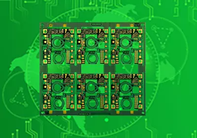
In modern electronic hardware architecture, printed circuit boards rarely operate as completely isolated islands. Whether powering an industrial robotic arm, transmitting sensor telemetry inside an electric vehicle, or routing user commands from a appliance control panel, sub-assemblies must communicate cleanly with off-board modules. These critical physical interfaces depend on sturdy wire-to-board interconnect systems to transfer power, ground, and multi-gigabit data signals seamlessly across internal chassis boundaries. Selecting the appropriate PCB board-to-wire connectors is a fundamental engineering step that directly dictates product durability, assembly line efficiency, and field serviceability. By bridging the structural gap between rigid copper tracks and flexible insulated wire harnesses, these components ensure that electrical systems maintain uninterrupted performance under real-world mechanical stress.
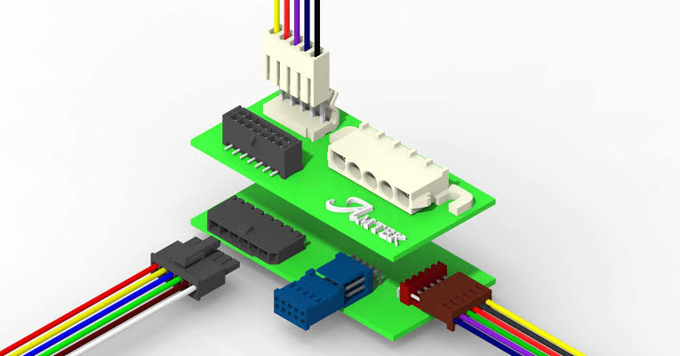
pcb board to wire connectors
Key Types and Mounting Options
Wire-to-board systems consist of two primary mating halves: a male header soldered directly onto the printed circuit board substrate, and a removable female socket housing loaded with crimped wire terminals. The male headers come in two predominant mounting configurations depending on the mechanical demands of the end application.
Through-hole headers feature metallic pins that extend entirely through drilled holes on the board, securing them firmly with solid solder barrels. This traditional style provides exceptional mechanical retention, making it the preferred choice for heavy-duty power lines or interfaces that experience frequent manual plugging and unplugging. Conversely, Surface Mount Technology (SMT) headers sit directly on surface pads. SMT headers are ideal for high-density, automated assembly lines where saving board real estate and reducing manual soldering labor are top priorities.
Critical Selection Criteria for Engineers
When designing an interface harness, selecting the correct PCB board to wire connectors requires a balanced evaluation of electrical parameters, physical pin spacing, and environmental resilience.
---Pin Pitch and Board Space: Pin pitch defines the distance from the center of one contact pin to the center of the adjacent pin. Micro-pitch variants, such as 1.0 mm or 1.25 mm, are essential for ultra-compact consumer devices where every millimeter counts. Larger pitches, like 2.54 mm or 3.96 mm, provide thicker contact pins and higher isolation gaps needed to prevent high-voltage arc-over between adjacent conductors.
---Current Rating and Thermal Management: Contact pins must carry target electrical currents without generating excess resistive heat that could melt the surrounding plastic insulation housing.
---Locking Mechanisms: In high-vibration settings, passive friction latches may gradually back out over time. Engineers specify active positive friction locks or latching arms that audibly click into place, ensuring the harness stays securely mated despite continuous shaking.
Primary Industry Applications
Because of their versatile adaptability, heavy-duty pcb board to wire connectors are widely integrated across virtually every major hardware sector.
In industrial automation, Programmable Logic Controllers (PLCs), stepper motor drivers, and power distribution units rely on heavy-duty wire-to-board interfaces to deliver high current directly from main transformers to control boards. In the automotive market, electric vehicles employ these robust connectors inside Battery Management Systems (BMS) to collect voltage and temperature readings from individual lithium battery cells. Furthermore, in the consumer market, smart home appliances, 3D printers, and HVAC units utilize standardized ribbon cable headers to connect human-interface display boards to main logic motherboards quickly and cost-effectively.
Installation Best Practices and Maintenance
Achieving long-term electrical stability requires strict adherence to assembly guidelines during both manufacturing and harness crimping stages. Using specialized PCB board to wire connectors equipped with mechanical keying and polarization features prevents operator error, ensuring that harnesses cannot be plugged in backwards or misaligned during fast-paced factory assembly.
Equally crucial is the precision of the crimping process. The metallic terminal barrel must be crimped around the stripped wire strands with calculated force to form a gas-tight mechanical cold weld. A loose crimp introduces elevated electrical resistance, leading to localized heating, voltage drops, and intermittent signal losses over time. Additionally, applying strain relief mechanisms—such as securing the wire bundle to the outer housing or chassis frame—prevents mechanical pulls on the individual crimp joints, dramatically extending the operating life of the interconnect system.
Conclusion
Building high-performance electronic hardware requires equal attention to internal board traces and external interconnect interfaces. While silicon chips and circuit board stackups receive significant design attention, a single loose pin connection on an unlatched header can compromise an entire system out in the field. Specifying robust PCB board to wire connectors tailored to your project's voltage levels, vibration profile, and spatial limits guarantees smooth power delivery and crisp signal integrity over years of continuous operation. By prioritizing positive locking features, precise crimp terminal quality, and proper pin pitch configurations early in the prototype phase, your engineering team can streamline manufacturing turnaround times, simplify field repairs, and deliver exceptionally reliable products to market.