A Trustworthy PCB and Electronic Manufacturing Enterprise! Contact Us



As modern electronic components grow smaller while demanding higher power outputs, internal thermal management has become one of the most critical challenges facing hardware engineers. High-power LEDs, motor drivers, and industrial power supplies generate localized heat that can quickly degrade silicon components, reduce power efficiency, and cause total system failures if left unchecked. Standard FR4 fiberglass boards serve as poor thermal conductors, effectively trapping heat underneath power devices. To bypass this thermal bottleneck, designers are turning to specialized insulated metal substrates. Integrating a high-performance aluminium PCB circuit board into your hardware package provides a solid metallic thermal bridge, transferring excess heat away from active chips rapidly to keep operating temperatures cool and overall performance perfectly stable.
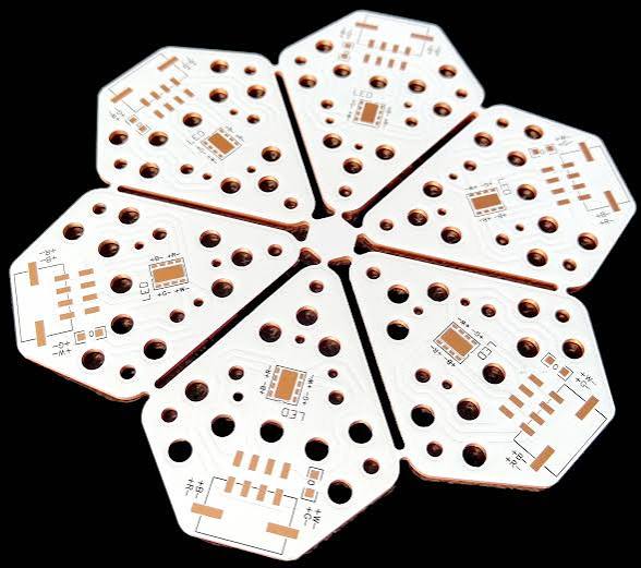
aluminium pcb circuit board
The Three Layer Architecture of Aluminium Substrates
Unlike standard multilayer fiberglass boards, an aluminium substrate relies on a specialized three-layer sandwich construction specifically engineered to maximize thermal transfer while preserving electrical isolation.
---The Circuit Layer: This top layer features standard etched copper foil, ranging from standard 1oz up to heavy 3oz or 4oz copper thicknesses, used to route electrical signals and mount components.
---The Dielectric Layer: Situated directly beneath the copper trace layout, this layer represents the true heart of metal substrate technology. It is composed of a specialized epoxy polymer infused with ceramic fillers. This layer provides extreme electrical insulation to prevent short circuits while maintaining exceptional thermal conductivity ranging from 1.0 W/m·K up to 8.0 W/m·K or higher.
---The Aluminium Base Membrane: The bottom foundation consists of a solid aluminium alloy plate (typically 5052 or 6061 grade). This metal backing serves as the primary structural heatsink, absorbing thermal energy from the dielectric layer and releasing it evenly into the ambient air or an attached external cooling chassis.
Outstanding Thermal Dissipation and Mechanical Durability
The core advantage of choosing an aluminium PCB circuit board over a traditional FR4 substrate is its dramatically superior thermal dissipation capacity. Aluminum conducts heat up to ten times more effectively than standard fiberglass matrix composites. By moving heat directly away from delicate silicon junctions, operating temperatures remain well within safe working parameters, preventing premature component aging and catastrophic thermal runaway.
Beyond thermal benefits, metal core substrates offer superior mechanical stability. Traditional glass-epoxy boards can warp, flex, or crack under intense physical shock or prolonged exposure to high ambient heat. Aluminum bases provide exceptional dimensional stability, retaining their structural shape even across extreme thermal cycling. Furthermore, the Coefficient of Thermal Expansion (CTE) of aluminum aligns much closer to metallic solder alloys and electronic components than FR4 does, significantly reducing mechanical shear stress on surface-mount solder joints during heating and cooling cycles.
Key Industry Applications
Thanks to its unmatched combination of heat dissipation and structural strength, the aluminium PCB circuit board has become the industry standard across several high-power electronic sectors.
The primary market for metal-core boards is High-Brightness LED (HB-LED) lighting. Modern automotive headlights, urban street lamps, stadium floodlights, and commercial architectural light strips generate substantial heat behind their dense LED arrays. Mounting these diodes directly on aluminum substrates prevents thermal throttling and ensures consistent color temperature and lumen output over tens of thousands of operating hours.
In addition to lighting, power conversion electronics rely heavily on metal boards. Switching Power Supplies (SMPS), DC-DC converters, solar inverters, and motor drive controllers inside modern electric vehicles (EVs) utilize aluminum substrates to manage heat generated by high-current MOSFETs and IGBTs, reducing the need for heavy, expensive external fan assemblies.
Design Considerations and Manufacturing Best Practices
When laying out an aluminium PCB circuit board system, engineers must adapt their design approaches compared to standard FR4 boards. Most metal core designs utilize a single-sided layout where all components sit on the top copper foil, leaving the flat aluminum back face entirely clear to mate flush against a metal enclosure or heatsink.
Because the underlying metal base is conductive, electrical clearance and creepage distances between copper traces and board edges must be meticulously calculated to avoid high-voltage arc-overs. Furthermore, routing through-holes entirely through the metal layer requires specialized isolation insulation steps, making surface-mount components (SMT) the preferred choice. During fabrication, manufacturing plants utilize specialized diamond-coated cutting tools or precision scoring systems to cut through the tough metal backing cleanly without leaving rough burrs that could compromise flush heatsink contact.
Conclusion
Tackling high thermal loads is essential for building durable, reliable, next-generation electronic hardware. Relying on outdated cooling methods or under-specifying thermal substrates ultimately leads to early field failures and damaged brand reputation. Utilizing a custom-engineered aluminium PCB circuit board provides the ultimate structural and thermal bridge, rapidly sinking heat away from high-power components and ensuring stable operating conditions even in punishing physical environments. By balancing dielectric layer insulation specifications with proper copper foil weights early in the design cycle, your product development team can eliminate bulky external cooling hardware, shrink overall device footprints, and deliver exceptionally reliable power electronics to market with total confidence.